Load Bank Test Rig
At QR’s Redbank workshops, building after building is dedicated to specific roles in the maintenance and re-build of trains for the suburban and state-wide rail networks.
Tucked to one side on this huge facility is a building known as the Load Box. Spectacularly unattractive from the outside and separated from buildings across the way by huge sound proofing doors intended to contain the noise of the locos performing under load, the Load Box comprises a control room, two test bays, a water load tank and until very recently, an aging DC resistor load bank. Here the diesel-electric locos are brought following overhaul, refurbishment or modification to be operated under load to verify that they meet their respective performance criteria. The load testing can also be used to simulate specific operating conditions which can assist in fault finding. Understood to be the only facility of its type in the southern hemisphere, some 200 locomotives are processed through the Load Box annually.
The locomotive generator output is connected to a variable resistance load bank which is configured to obtain the desired operating condition for the required tests. Measurements can include: engine temperatures, pressures, fuel flows, RPM, control voltages/currents and generator voltage and current.

Replace Existing Load Bank
Several years ago QR decided that the existing load bank, which had been in service since 1964, needed to be replaced. In a state of disrepair, its continued use was considered to be unsafe. Originally manufactured with the capability of incrementing load in 24 steps, its condition had not allowed the changing of steps for quite some time.
QR determined that the new load bank should be controlled by the PLC/SCADA system incorporated within the load box control consoles. The original 24 steps could be condensed to 10 steps. In view of potential future overhauls of higher classes of Diesel-Electric Locomotives, the proposed upgrading had to have the capability to test 2800 and 4000 class.
With this in mind, QR’s engineers sought the assistance of Chase Power Pty Ltd to write a functional design specification for the proposed new equipment. Chase Power specialise in providing engineered solutions and power quality equipment to their customers throughout Australia, New Zealand and the Pacific region.
Preferred Turnkey Solution
With the specification for a replacement load bank written, QR released the tender worldwide. Whilst companies from the UK and Europe were keen to offer their resistor expertise, only Chase Power were able to offer the turn-key solution QR required.
Chase Power were contracted to design, supply, install and commission the new 2500V, 4000A DC Load bank, Switchboard and PLC programming, and to train the QR team in its operation. They teamed with local sub-contractors to deliver the specialised equipment which was designed and built in Brisbane, Australia.
Housing Design Constraints
Situated above the control room on a mezzanine level and accessed only via a vertical ladder beside one of the test bays, removal of the existing load bank and installation of the new was to prove challenging. The old load bank was taller than the access doorway and extremely heavy. Following de-commissioning, a crane was used to remove the existing and to lift the new equipment to the mezzanine level. A lack of head room saw some creative removal of non-essential ceiling timbers. Skates and birt bars were employed to jockey the equipment into position.
The room seemed spacious when it housed the original load bank, but presented the Chase design team with real space constraints when faced with fitting the new load bank, cooling fans, exhaust ductwork and switchboard.

Load Bank Design Challenges
QR’s load bank requirements were somewhat unique in that each of the 10 required steps had a different voltage, which meant adding or subtracting a bank of common resistors to fit the kW rating required for each of the steps was not feasible. An economical method of sharing resistors between steps without exceeding the watts densities and temperature limits of the resistors had to be found.
Care was taken to limit the number of resistor voltage ratings utilised in the system design in order to minimise the number of spares that would have to be carried, as well as the long term maintenance costs. The final design of ten steps of different voltages with a combined load of 16.5 MW was achieved using 480 x 15 kW resistors, a total of 7.68 MW using resistors with only 3 different voltage ratings.
In responding to the challenge of designing a system that would fit into the limited space available, firebar resistors were chosen. These resistors were considered most suited due to the rectangular geometry cross section area which enables the fitting of 38% more kilowatts than resistors of the round tubular shape. The flat surface geometry also allows better heat transfer for forced cooling air, whilst the surface is not impaired by back eddies inherent in the round tubular shape.
Safety alarms were provided for forced cooling air flow, resistor over temperature and terminal box over temperature.
The load bank was designed in a modular form for easier handling and installation. Five separate modules were built and fitted together on site.
Modular Switchboard System
Whilst there are many Australian switchboard manufacturers and suppliers of switchboard accessories such as busbar supports, insulators etc. most of their products are designed to suit three phase AC systems. The 2500V, 4000A DC switchboard presented different design challenges. To suit the site conditions and meet the project time frame a modular switchboard system was adapted and most of the internal accessories were designed and manufactured specifically for this application.
The switchboard needed to be front connected and constructed in an L shape to fit into the corner of the room. The existing main cables enter from the rear and the load bank cables exit through the top of the switchboard. QR’s specification required that the Main Isolator Contactor have a peak load-breaking capacity of at least 1000A DC and for safety, the contactor had to be mechanically latched to prevent accidental opening during a test above 1000A DC. Highly specialised switchgear was manufactured for the project in Italy. To minimise project delays, design of the busbar system and switchgear mounting had to allow for last minute fine tuning, so that the manufacture could proceed while waiting for accurate information with regard to mounting and connection details.
To prevent on load switching, provision was made for electrical interlocking in the step switch control circuits in accordance with the control philosophy.
PLC Programming
Whilst the original load bank was operated manually, QR’s specification tasked Chase Power with integrating the new automated load bank system into an existing PLC/SCADA system.
The existing PLC/SCADA automation system consisted of two Allen Bradley SLC505’s, networked via Ethernet to two Citect SCADA servers. The extent of use of this system was for data acquisition and trending of testing parameters.
QR’s Test facility comprises two test bays, each of which has its own PLC and Operator station. A requirement was placed on the control system designs that either of the Test bays could operate the load bank – but only one system at a time. Further the PLC systems were required to operate independently, so that if one PLC was shut down the other PLC would still be able to operate the load bank.
Hardware Solution
As QR’s preference was for Allen Bradley hardware, remote compact Block I/O was chosen for the load bank controls. The communications bus implemented was DeviceNet. The remote I/O is responsible for switching the motorised contactors and isolators (including interlocks) in the switchboard feeding the load bank providing position feedback, controlling cooling fans, various interlocks and alarm conditions.
A design challenge required the two DeviceNet master scanners to be able to simultaneously communicate to the CompactBlock I/O. Two solutions, hardware and software, were considered.
A complex software solution had been achieved by others on a Control Logix platform, but no tried solution existed for the SLC platform. Due to the untested nature and possible software complexity that would have to be supported by QR, a decision was made to proceed with a hardware solution.
PLC code was written, tested, implemented and commissioned. Some existing control circuit faults were identified and these were coded out in the PLC program. Citect SCADA screens were developed to give the operator remote control over the load bank system and to provide system status.
Achievements Summary
A vast improvement in the labour efficiency of the old system from a controls perspective, with the operator never having to leave the control room to adjust the load bank. Hardware and software licence savings were also realised as the existing PLC, SCADA and operator stations were utilised.


Bar Mounted Contactors

Final Handover

L-Shaped Modular Switchboard

Load Box Control Room

Safety At All Times
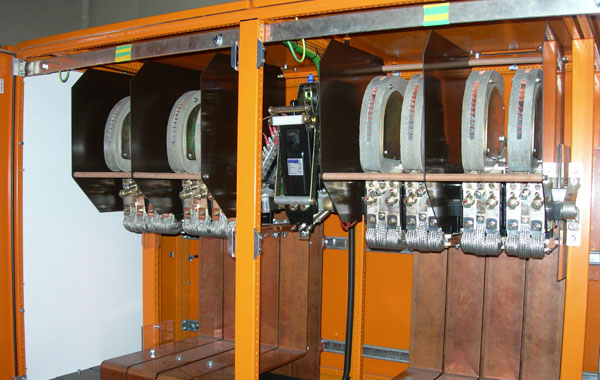
Mechanically Latched Bar Mounted 4000A Contactors
